MAIN FEATURES
- Made of stainless steel or galvanized sheet metal;
- Adaptable to all situations
- Quick and easy to mount
- Pleasant and innovative design
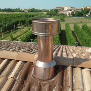
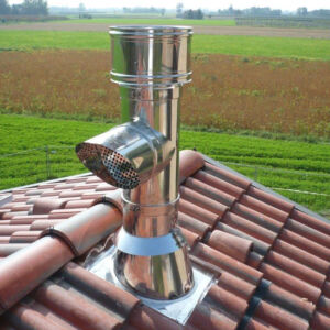
The Architectural Terminals/Chimeny Cap series produced by Fibrotubi S.r.l. includes all those devices that, placed on the end of a chimney/flue, allow dispersion of the stack effluents even when atmospheric conditions are bad. The features that characterise this series are:
- a useful outlet section that is no less than double that of the chimney/flue it is fitted on;
- so shaped to stop any rain and snow from getting inside the chimney/flue;
- it is made so that, even with winds from any direction or angle, the evacuation of stack effluents is always guaranteed.
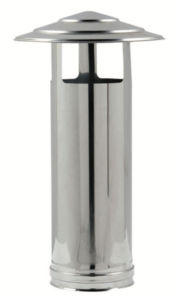
Terminal with single-wall stainless steel windows (also with female plug)
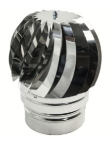
Ventilator chimney cowl

STAINLESS STEEL converse for expanded clay chimneys
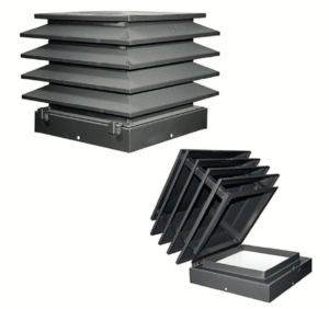
Tek Inspectionable terminal
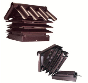
Coppo Inspectionable terminal
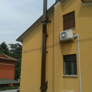
It is possible to create a flue duct building a chimney with the elements in expanded clay using the terminal converse that connects and allows the fitting of the stainless steel chimney using the appropriate locking clamp.

3 Stainless steel chimney
2 Locking clamp
1 Stainless Steel Converse

NOTE: Also available to complete the terminal/chimney, flat and/or sloping converse from 15° to 20° with waterproof membrane.

Remember that the chimneys must have no mechanical suction aids and, moreover, it is also important to remember that the outlet height is found by measuring the minimum height between the roof covering and the bottom point where the smoke/fumes are let into the atmosphere.
For suction pressure flue systems, this height must be outside the so-called minimum distance to avoid the formation of back pressures that would impede the free evacuation of stack effluents into the atmosphere.
Windproof chimney cap: ζ 1.54 (Istituto Giordano S.p.a. test report no. 195699)
| Chinese chimney cap: Extract of Table B.8 13384-1 year 2004: | ||||
| 9 | Rain guard |  |
H/D | ζ – values |
| 0,5 | 1,5 | |||
| 1,0 | 1,0 | |||
Aerodynamic behaviour of the terminal (end part) in windy conditions: NPD
POSITIONING OF CHIMNEYS AND/OR TERMINALS ON BUILDINGS WITH >10° (17.6%) SLANTING ROOFS

| Symbol | c | a |
| Description | Distance measured 90° from the roof surface (mm) | Height above the roof ridge (mm) |
| Minimum air | ||
| Flue system working with negative pressure | 1300 | 500 |
| Flue system working with positive pressure | 500 | 500 |
| Flue system working with positive pressure | 500 | 500 |
POSITIONING OF CHIMNEYS AND/OR TERMINALS ON BUILDINGS WITH >10° (17.6%) SLANTING ROOFS IN RELATION TO DORMERS AND SKYLIGHTS

| Symbol | Dormer | Skylight |
| Description | A= Side distance from the dormer B= Height above the ridge of the dormer structure L= Front distance from the dormer | D= Distance from the top or side edge of the openings or windows D= Distance from the bottom edge of openings or windows V= Height above an opening or windows |
| Minimum distances | ||
| Flue system working with negative pressure | A= 1500 / B= 1000 / L= 3000 C= 1000 / D= 3000 / V= 1000 |
|
| Flue system working with positive pressure | A= 600 / B= 600 / L= 2500 C= 600 / D= 2500 / V= 1000 |
|
| Flue system working with positive pressure | A= 600 / B= 600 / L= 2500 C= 600 / D= 2500 / V= 1000 |
|
POSITIONING CHIMNEYS AND/OR TERMINALS ON BUILDINGS WITH FLAT ROOFS IN RELATION TO WINDOWLESS EQUIPMENT VOLUMES
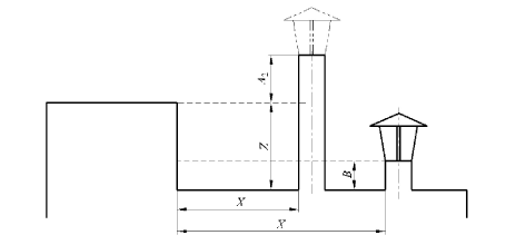
Outlet heights in relation to the distance of the end part of the windowless obstacle
| Negative pressure | Positive pressure | ||
| Distance (mm) | Outlet height | Distance (mm) | Outlet height |
| X ≤ 2000 X > 2000 |
Z + A2 B |
X ≤ 1200 X > 1200 |
Z + A2 B |
With symbol Z we mean the height (mm) of the obstacle or equipment compartment; as regards to heights A2 and B see prospectus 1.1 (UNI 7129 part 3)
Outlet height indication:
| Symbol | A2 | B* |
| Description | Height above the virtual pitch between the roofs of buildings or adjacent obstacles or equipment compartments with no openings/windows | Height above flat roofs or closed railings |
| Distances to be observed | ||
| Negative pressure | 500 | 1000 |
| Positive pressure | 500 | 500 |
| Extraction hoods | 500 | 500 |
POSITIONING CHIMNEYS AND/OR TERMINALS ON BUILDINGS WITH FLAT ROOFS IN RELATION TO EQUIPMENT VOLUMES WITH OPENINGS

Outlet heights in relation to the distance of the end part of the windowless obstacle
| Negative pressurePositive pressure | |||
| Distance (mm) | Outlet height | Distance (mm) | Outlet height |
| X = 3000 3000 < X = 5000 X > 5000 |
Z + A2 J B |
X = 2500 2500 < X = 4000 X > 4000 |
Z + A2 J B |
If there is a balcony or terrace (instead of just a window), distance X must be calculated starting from the balustrade (closed or open whatever) and not from the wall of the building. With symbol Z we mean the height (mm) of the obstacle or equipment compartment.
 |
DARK BROWN MATT DAMASK EFFECT (RAL 8017)If temperatures exceed 250° (on the outer surface) the paint could flake and come off. |
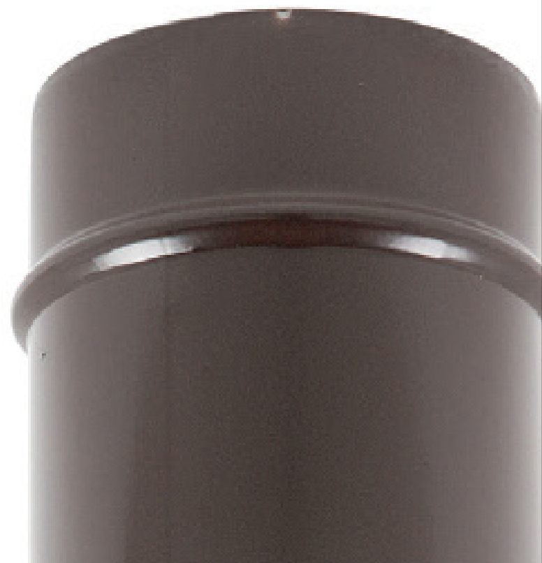 |
OUTER SURFACE FINISH IN MATT DARK BROWN (RAL 8017)If temperatures exceed 250° (on the outer surface) the paint could flake and come off. |
 |
OUTER SURFACE FINISH IN BLACKIf temperatures exceed 450° (on the outer surface) the paint could flake and come off. |
 |
OUTER SURFACE FINISH IN WHITE (RAL 9010)If temperatures exceed 250° (on the outer surface) the paint could flake and come off. |


